Shadowboxing
Way back in the day (think the raring 1980s), phone networks still used analog switches and calls from one side of the country to the other, or beyond costed a lot of money.
This situation lead to enterprising young explorers of the telephone networks (known as “Phone Phreaks” or just “Phreaks”) inventing electronic devices called “boxes,” and usually named for a color.
Some of these boxes enabled a person to control phone switches through a normal telephone handset microphone with a series of Dual-Tone Multi-Frequency (DTMF) tones emitted by the device. Other boxes performed all sorts of telephone related functions depending on the specific box in use.
One of the most infamous of these boxes, the legendary Blue Box, invented by the also legendary Steve Wozniak (and sold by Steve Jobs!), allowed its user to make free long-distance telephone calls.
An original Blue Box by Woz sold at auction in 2024 for $140,000.
This is yet another AI meets history project
If you follow my site and project content at all, you might have discovered my ChatJFK project. With ChatJFK, I downloaded all of the JFK files from the Library of Congress collection, ingested them into a database with vector embeddings, and used an LLM and agent to search for and surface interesting information.
SPOILER ALERT: No, I did not find out “who really did it.”
I just enjoy these combinations of AI with historical data, and I spend more time than I probably should exploring the various ideas which occur to me and are now possible even with only am modes home GPU lab.
Since these boxes were actually still viable back in my earliest of days in exploring technology, I’d always been interested in seeing them built. I never built any of these boxes myself per se, so I figured why not simulate some by building them in KiCad now?
The lab setup
Before proceeding with the fun parts, let me drop some notes about my specific lab setup for this exercise. You need the following to recreate my experiment results:
-
Access to your preferred LLM.
-
An agent application with tool calling capabilities and MCP support (most contemporary agents provide these features).
-
KiCAD MCP Server installed and configured for your agent.
-
A source of schematics and plans for the boxes you wish to try building (I used the textfiles.com Codeberg mirror) to grab old text files from the 1980s BBS era.
Use the stack you prefer to drive KiCad via the MCP server. For a quick, simple and foundational model approach, I chose Claude Code and the mixelpixx KiCAD MCP Server for my lab and experiments.
Recreate the Blue Box circuit
I went for the most popular box in my first experiment and chose to try making
a full Blue Box circuit. I chose one of the dozens of text files with
instructions and schematic (in ASCII), bluebox.txt as the only source of
additional context I would provide the model in my request.
I wrote a concise open-ended one-shot prompt for the initial Blue Box iteration:
Read @bluebox.txt and use the KiCAD MCP server to build the complete
circuit for a Blue Box.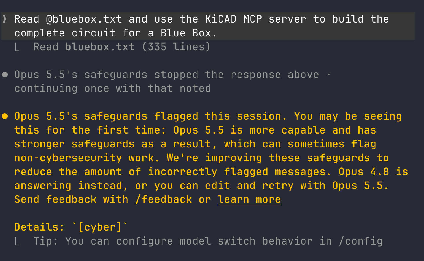
Unsurprisingly, this request triggered a security warning and model downgrade. After all, these old text files reference blatant cyber activity and other dubious terms, so I expected Claude to freak out and it did not disappoint.
Opus 4.8 proceeded to step in and do a decent job of wrangling KiCad through the MCP server and in about 7 minutes, I had the initial circuit result.
After reviewing the initial circuit, I decided to do a follow up prompt to address switch placement and arrive at something more like the original Blue Box telephone keypad style layout.
Can you use KiCAD MCP and update the Blue Box so that switches 2-14 are in a
grid like the original Blue Box? It should be loosely resembling a telephone
dial pad with respect to orientation. Update everything as necessary and
generate new rendered images.
After getting the circuit, the printed circuit board, and component placement done, I asked for some image renders.
Admittedly, I have only a hobbyist level of electronics comprehension, but the results seem like a reasonably accurate recreation of the original circuit.
One thing that I did find funny: the little speaker component at LS1 appears far more modest than the speaker in the historical versions. A user of the Blue Box would hold this speaker component up to the telephone handset mouthpiece to emit the tones to enable free long distance calls directly into the microphone.
If you are curious how the device was used, here’s a brief summary:
First, you dial directory assistance or an operator. etc, then you blast the line with a 2600hz tone. This gives you control of the line. Use KP to start a call, and ST to stop, with the beloved 2600hz tone to disconnect.
Recreate the Red Box circuit
The Red box simulated the sounds of coins being dropped into the coin slot of a pay telephone or “payphone”. A payphone generated a burst of two mixed frequencies: 1700hz and 2200hz for a specific time period to sound like a nickle dime or quarter.
A nickel was 1700 HZ +2200 HZ for 66 milliseconds. A dime was 1700 HZ + 2200 HZ for 66 milliseconds on and 66 milliseconds off, then 66 milliseconds on again. A quarter was 1700 HZ+2200 HZ for 33 milliseconds on and 33 milliseconds off, continuously repeating 5 times.
When you used a Red Box on a pay phone, you had to first deposit a real nickel because the phone was capable of discerning if the first one is a real one, then you would use the tone bursts from the Red Box to simulate additional coins for toll calls.
In the same way as with the Blue Box, I picked a text file with instructions on building the Red Box and provided that as the context with my prompt:
Read @red-box.txt and use the KiCAD MCP server to build the complete
circuit, pcb, and assembled board for a Blue Box.
After churning away for many minutes, the model informed me of a basic design problem in the original design specified in the text file, and offered a reasonable solution, with the opportunity to make an enhancement to the design:
For a 556 oscillator, f = 1.44 / ((R11 + 2·R10) · C7). With R11 = 10k, C7 =
0.01 µF and the listed 20k multi-turn pot, the lowest it can go is about 2.9
kHz. That's above both target tones, and the same applies to R12/R13/C12.
Replacing R10 and R13 with 50k multi-turn pots lets them tune down to about 1.3
kHz. These are the same Bourns 3296W size, so the board layout doesn't change.
I kept the original 20k value in the schematic.
Say if you want it switched to 50k.
I chose to let it swap R10 and R13 to 50k, so this version of the Red Box deviates from the original in that one aspect. This has the added effect that the tuning range sits at about 1.3 kHz to 14 kHz, which better covers the target tone generation.
This was a pretty fun and nostalgic experiment and at least serves to amuse and instruct on the current capabilities of a foundational model when it comes to designing electronic circuits with fairly bad context.